CNC mill
I first built this mill in 1993 from plans I bought via Usenet (“Robotic Woodcarver Kit #1”!) from a fellow named Andrew Cilia. I’m writing this in 2018, so, 25 years ago. The original software was DOS-based, written in pretty awful C. I quickly ported it to linux, but I never succeeded in making the code “not awful”. The controller required independent control of the individual stepper motor windings in software, and it was fairly convoluted.
Initial design
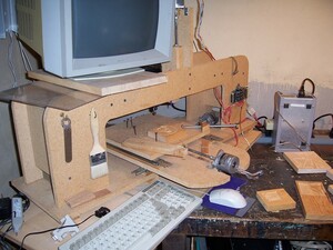
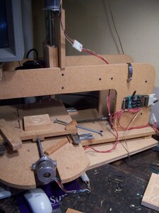
The first few pictures here were taken in 2006, just before I threw up my hands in disgust at not being able to get it working properly after a somewhat long hiatus from milling. I had by then switched to LinuxCNC as the driving software, having written a custom pin driver for my oddball controller.
The shaft couplings consisted of a 5/16” coupler locknutted to the threaded shaft, and hot-melt glued to the stepper shaft. This worked surprisingly well, if you could get everything aligned properly. That was always a big “if”.
Early carvings
Here are few of the more successful early carvings. (There were a lot
more unsuccessful one!) I believe the three on the
left were all made using my linux port of Andrew Cilia’s original software.
The other two were done using LinuxCNC. (The angel was hand-drawn by my
wife, photographed, converted to a high-contrast bitmap, and turned into
vector format with the “autotrace” program, and run through a vector path
optimizer I wrote, before being finally converted to gcode.)
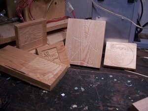 If you look carefully at the carving on the far right, you might think
that the circle isn’t round. You’d be right. The stepper on one of the
axes was missing steps, and so not traveling as far as it should have been.
At least it was consistent, so it usually ended up back in the same place
after a round trip.
Later modifications
The rest of the pictures were taken in 2015 or later.
The original plans called for a dremel tool as the spindle. That proved insufficient fairly quickly. I replaced it with a Porter-Cable laminate trimmer, which lasted for many years. It’s since been replaced by a Makita variable speed router, which, when run slowly, is much quieter.
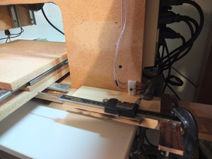
Here I’m using my digital caliper to figure out whether the X axis motor is
dropping steps. It was – the shaft needed to be cleaned and
straightened, and, eventually, replaced.
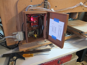
The original stepper controller was swapped out with a model from SparkFun, which works better with LinuxCNC. The new controller lives in the “electronics cabinet” – actually just an old cigar box.
I used a couple of ribbon cable connectors to form sort of a patch panel for doing the interconnect from the computers parallel port to the controller inputs. The terminal strip above the cigar box is for the limit switches and probe input.
The small receiver under the monitor is for my IR keyboard.
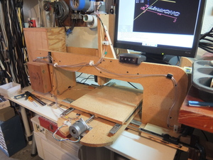
It’s handy not having wires – the (big) downside is that if you start a motion and happen not to be pointing the keyboard closely enough at the receiver when you release the key, the machine will keep on moving, since it never got the “key released” signal. That’s what prompted me to finally install limit switches!
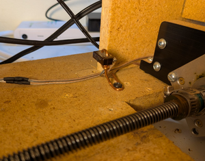
The limit switches are small microswitches I’ve had in my junk box for years.
Mounting them on little copper wire pedestals lets them
“give” a little, and lets me bend them out of the way if I need to
move the table a little further during maintenance.
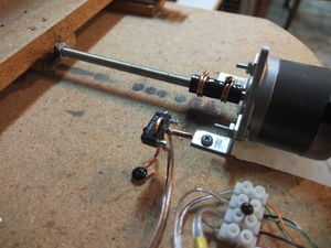
The shaft couplers (also in the photo above) are now short lengths of 1/4” braided rubber fuel line, clamped to the 1/4” stepper shaft and 5/16” threaded shaft with double twists of the same 12 guage copper wire.
The drawer slides (“Accuride”, I think?) work reasonably as transport
for the X and Y axes, but they were terrible for the Z axis. The problem
was that although they prevent motion well in the front-to-back direction
(the Y axis), there was a lot of flex in the right-to-left (X axis) direction.
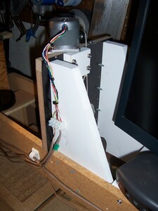
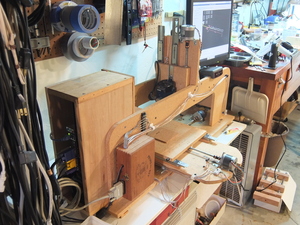 The Z axis has been rebuilt since this was taken. More pictures below.
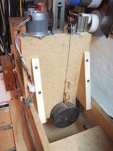
The laminate trimmer is a big load for the stepper to lift. A 4 pound
weight acts as a counterweight.
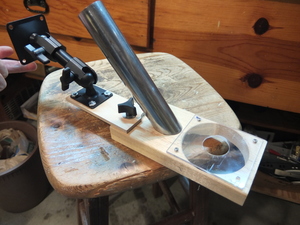
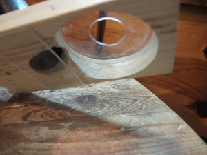
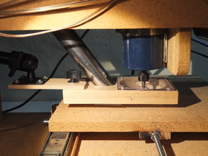
I made a dust collector from odds and ends I had around the shop. The shop vacuum attaches to the top of the chrome tube (which is from a section of sink plumbing that I had saved).
An advantage of having the Z axis fixed (rather than traveling back
and forth in the Y or X direction, in addition to going up and down)
is that the dust collector head also doesn’t move. So it can be
mounted separately from the cutting tool.
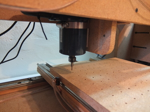
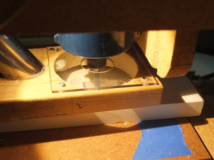
An “action” shot, actually milling, and collecting dust. Okay – not very
interesting, I know.
More carvings, 2015
Here are some projects from 2015, I think.
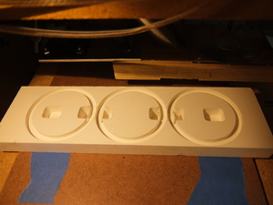
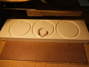
These are a couple of pieces from a project I carved from cellular PVC (i.e.,
Azek – the “plastic wood” that’s used a lot as exterior trim on houses
these days). It’s forgiving to work with, and easy to mill, but not
terribly structural.
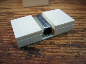
Here’s another part made from cellular PVC – it’s part of the shaft
mounting for the redesigned Z axis.
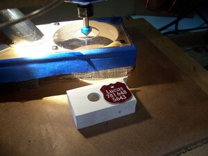
Usually I cut with an end-mill, which produces a square cut. With an angled
bit, engraving is possible, even in aluminum. Here’s
a new dog tag. Please don’t telephone me.
Rebuilt Axes
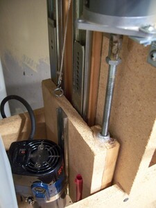
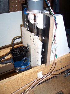
In 2015, it was time to replace some parts that were limiting performance quite a bit. As I mentioned, the Z axis had way too much flex, so I bought some ball rail slides to replace the drawer slides.
I used the mill itself to cut and drill pilots for all the holes in the new design, to allow accurate mounting of the new ball rail slides, and the mounting blocks for the router, the shaft coupler, and the stepper motor. It all went together really well.
I’m still using the pulley and 4 pound counterweight, because the coupling from the motor to the shaft isn’t all that strong. Way better to have that joint under some compression, rather than being pulled apart.
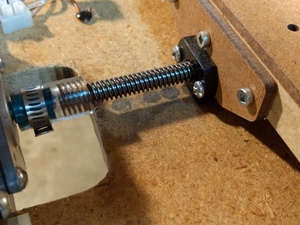
The drawer slides work “well enough” for the X and Y axes, since they’re well supported in the direction they’re most likely to flex. But the all-thread rods used to cause motion were terribly inefficient. I upgraded to Acme threaded rod, and tripled the top speed of the axes from 18 ipm to 54 ipm. This is still very slow for a CNC mill, but a huge improvement for me. (The Z axis, which still uses all-thread, will only run reliably at about 6 ipm.)
The rod-to-motor couplings still use sections of rubber hose. They’re surprisingly accurate.
The Z-axis probe
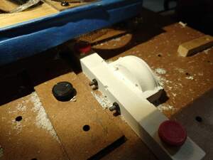
Sometimes it’s useful to be able to measure the contour of a surface
before carving it – you can then use that data to adjust the depth of
the carving. This can let you do a shallow etching on a board that’s
cupped or warped, for instance. My first Z-axis probe was fairly crude:
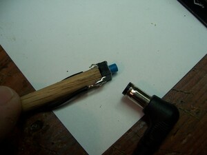
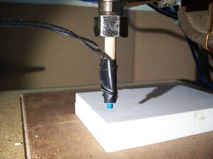
I’ve since rebuilt it, using a more accurate switch (and better
construction!):
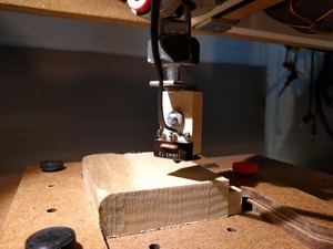
This switch gives reproducible readings that are +/- .0002”, which is far more accurate than the rest of the mill.
Game controller
Always having to pick up a PC keyboard to run the mill was a nuisance.
Many times all you’re doing is getting the cutting head out of the way,
or raising the router to change the bit.
I picked up a cheap USB game controller, and mapped its buttons to
move the axes, perform emergency stops, and few other frequent operations.
It’s a big help.
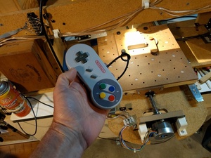
(But I’m going to need to spend more for a better controller. Sometimes when I ask for a positive Y motion, I get positive Z as well!)
Clamping and hold-downs
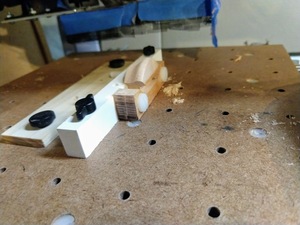
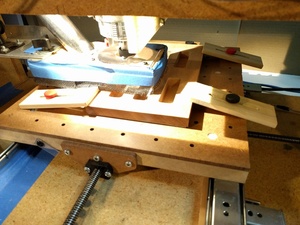
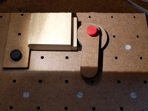
I’ve long needed a much better means of clamping workpieces to the bed of the mill. I had initially designed a bed of holes which could take pins, and had a screw clamp that could hold the piece sideways against the pins, but it never worked very well. So most of the time I used double-sided tape, which wasn’t bad for small parts, but terrible for big parts.
So in early 2018 I replaced the bed of the mill with a new piece of 3/4”
MDF. I drilled holes and installed #10-24 threaded inserts in all of them.
That piece is meant to be permanent. To protect it, it’s covered by a piece
of 1/4” masonite, drilled with matching holes.
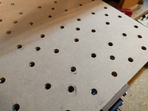
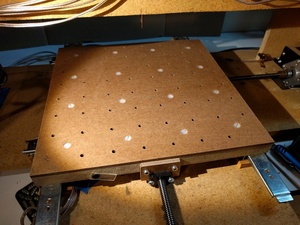
Some of those holes are used to secure
the masonite to the lower piece, and others just allow screws to access
the threaded inserts below. Various clamps and cam handles and stops
can now be easily attached to the mill, and parts being cut are held
securely.
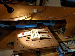
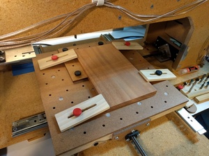
There was an amusing, and sad, side-effect of designing this new hold-down system. I quickly discovered that the X and Y rows of holes I’d drilled weren’t at right angles!! It turns out that my X and Y axes have never been quite properly mounted. For much of the time the problem was completely masked by the intermittent loss of stepper motor steps. When I fixed that problem, things were so much better that I think I didn’t do very careful measurements. They were only off by about 1%, but still…
In any case, it turns out there was a simple solution. Rather than disassembling and adjusting the X-axis drawer-slides, which would have been quite difficult, I took advantage of the fact that this is a CNC mill and fixed the problem… in software. With some pointers from the folks on the LinuxCNC forum, I was able to square up my axes in a few hours.
Yet more carvings, 2018
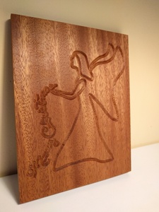
One of the first things I carved years ago was a Christmas angel.
There’s a picture of that old version above. With improvements to the
mill, and to my technique, a she looks a lot better than she did back
then. Splurging for mahogany didn’t hurt.
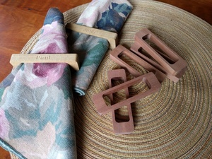
I’m pleased with these napkin rings. The lighter ones are poplar. The darker ones are mahogany. They haven’t been oiled yet – they’ll look like the angel, above, when they are.
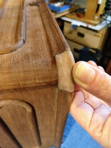
New trim for an antique sewing machine, winter 2020/2021
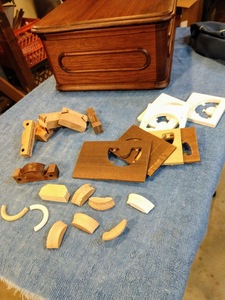
When I got my 1866 Grover and Baker sewing machine, the woodwork was in very good condition, but it was missing several pieces of trim from the bonnet top.
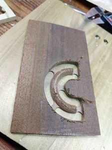
I was able to recreate those fairly accurately using the CNC mill. I luckily had some old (1870s) walnut to work with.
In this picture, you can see the new curved trim piece on the right, still
unfinished. I think it was missing two or three of these.
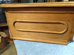 You can also see a missing corner piece at the lower right. It was
missing two of those.
It took a lot of “rough drafts”, but when I look at the finished
bonnet top today [written a couple of years later], I’m hard pressed
to tell which pieces are mine, and which are original.
Brain transplant, March/April 2025
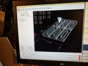
The PC that was running the mill was getting a little long in the tooth: the software it was running (LinuxCNC 2.7.4 on Debian Wheezy) was out of date by many years, and I thought it couldn’t be upgraded, because I was convinced (incorrectly, it turned out) that it was a 32 bit machine. The world has moved on. As it turned out, I realize later that it was actually a very early one-core 64 bit machine from AMD, but still, it only had 2MB of memory. Time for an upgrade anyway!
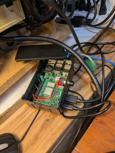
I had a spare Raspberry Pi 4, and LinuxCNC now supports that with its
 own pre-built distro. The only problem is that the RPi doesn’t have
the real-time latency capabilities of most PCs, so it’s not capable of
running stepper motors smoothly. (When running steppers, all of the
motors need new instructions tens of thousands of times per second,
and at extremely precise intervals.) The answer is to off-load that
lowest layer of the motion code to dedicated hardware, leaving the RPi
with the job of planning movements at a higher level, with much less
stringent timing requirements.
So I got a stepper controller card from Mesa. It uses a dedicated
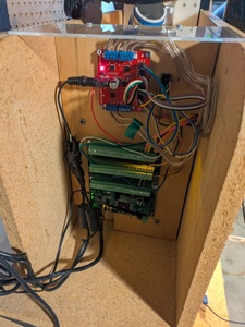 point-to-point ethernet segment to connect to the RPI. A very
simple protocol, long supported by LinuxCNC, sends data to and from
the stepper motors, and to/from the I/O lines which control and
monitor the mill. (BTW, I’m not proud of that wiring job. It’s
because there are a bunch of jumper wires going from place to place,
and they’re a little difficult to organize neatly.)
I also had to give the mill a bigger nicer monitor, because the
Raspberry Pi only has HDMI out. What a shame, eh? (To be clear, I
already owned it – I didn’t buy this mill that monitor. ;-)
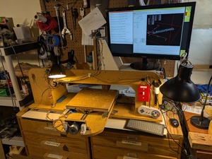
Oh! I also installed a new E-stop switch. Flashy!
End of an era, late April 2025
My 32 year old mill failed me one too many times last week.
I’d been making a bunch of improvements lately: the new RPi controller, a Mesa card interface, M3/M5 spindle control, M7/M9 vacuum control, some new hold-down techniques, automatic X/Y homing, better E-stop switch, probably some other stuff. It had been a while since I’d spent much time on it, so I was having a lot of fun.
And then the Z-axis shaft coupling broke away from the carriage in the middle of the final “good” carve for a project I was doing for Julia, and ruined the last piece of lumber we had on hand for a job on a very short schedule. Because the Z carriage was designed by an amateur (me), the problem was very difficult, if not impossible, to fix, without a full rebuild. It was the last straw. (Happily – we were able to rescue her project, but only barely, and with hand tools.)
So I’ve ordered a new mill. It will be here in a few days. Probably should have done it years ago.
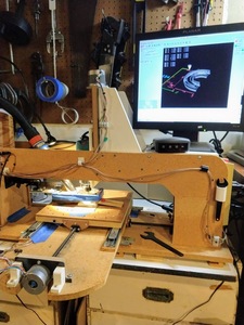
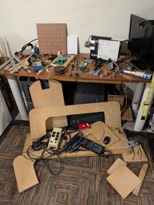
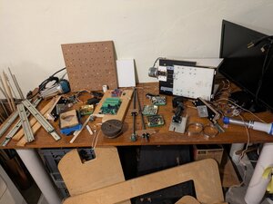
But that means I needed to make room. This only took an hour or two, which is ironic, considering the hundreds of hours I think I’ve put into it over the years. (Scroll up for a “before” picture”.) It was a little bit archeological, since as I took more and more apart, I kept getting to things I’d put together longer and longer ago. Cathartic, in a way.
In the end , I think one of the things I’ll miss most about that mill were the limit switches. You’ve gotta admit, this is cute, right? :-)
The End
