I jury-rigged a small circuit to read the reed switch pulses while the
motor turned -- I needed to know how fast the motor was going, and wanted
to use my oscilloscope to do so. (There are lots of ways to do this.)
A pair of resistors (values don't matter much -- they should be at
least 5K each, and not too dissimilar) were connected as a voltage
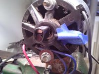
divider. The switch (the thing with black wires leading to the white
connector) was connected across one resistor. The scope measured the
voltage across the other resistor. The two ends of the voltage
divider were connected to a 5V wall-wart power supply.
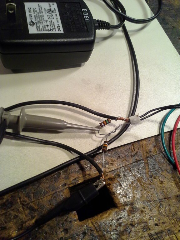
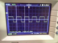
I jury-rigged a small circuit to read the reed switch pulses while the motor turned -- I needed to know how fast the motor was going, and wanted to use my oscilloscope to do so. (There are lots of ways to do this.) A pair of resistors (values don't matter much -- they should be at least 5K each, and not too dissimilar) were connected as a voltage divider. The switch (the thing with black wires leading to the white connector) was connected across one resistor. The scope measured the voltage across the other resistor. The two ends of the voltage divider were connected to a 5V wall-wart power supply.